Ultrasonic Pulse Velocity Test: its 5 Procedure Steps, Formula, & Advantages
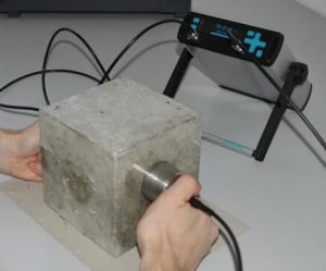
The Ultrasonic pulse velocity test is used to examine the quality of natural rocks and concrete and by measuring the velocity of an ultrasonic pulse passing through a natural rock formation or concrete structure, the strength, and the quality of concrete or rock are assessed in this test.
By passing a pulse ultrasonic through concrete to be tested and measuring the time taken by the pulse to get through the structure, an ultrasonic pulse velocity test is conducted.

The slower velocities may indicate concrete with many cracks or voids while higher velocities indicate good quality and continuity of the material.
Equipment:
There are the following equipment used in ultrasonic pulse velocity tests such as;
- It includes a pulse generation circuit consisting of an electronic circuit for generating pulses.
- A transducer for transforming electronic pulse into mechanical pulse which has an oscillation frequency in the range of 40 kHz to 50 kHz.
- For receiving the signal it includes a pulse reception circuit.

For use, the transducer, clock, oscillation circuit, and power source are assembled and the transducers are placed on opposite sides of the material after calibration to a standard sample of the material with known properties.
The Formula for Pulse Velocity:
There is a simple formula for measuring the pulse velocity as given below;

Procedure for Ultrasonic Pulse Velocity Test:
There are the following steps in the ultrasonic pulse velocity test as given below;
- Preparing for Use
- Set Reference
- Range Selection
- Pulse Velocity
- Separation of Transducer Leads
Preparing for Use:
The transducers should be connected to the sockets marked “TRAN” and “REC” before switching on the V meter and the V meter either be operated with;
- The internal battery
- An external battery
- The A.C line
Set Reference:
To check instrument zero, a reference bar is provided and on it, the pulse time for the bar is engraved. Before placing it on the opposite ends of the bar apply a smear of grease to the transducer faces.
Until the reference bar transit time is obtained on the instrument read-out adjust the ‘SET REF’ control.
Range Selection:
It is recommended that the 0.1-microsecond range should be selected for path lengths up to 400mm for maximum accuracy.
Pulse Velocity:
Make careful measurement of the path length ‘L’ and to the surfaces of the transducers apply couplant and onto the surface of the material press it hard.
While reading is being taken do not move the transducers because in measurements this can generate noise signals and errors. Until a consistent reading appears on the display which is the time in microsecond for the ultrasonic pulse to travel the distance ‘L’, continue holding the transducers onto the surface of the material.
When the unit digit hunts between two values the mean value of the display readings should be taken.

Separation of Transducer Leads:
To prevent the two transducer leads from coming into close contact with each other when the transit time measurements are being taken it is suitable.
If this is not done the receiver lead might pick up unwanted signals from the transmitter lead and an incorrect display of the transit time occurs.

Applications of Ultrasonic Pulse Velocity Test:
There are the following applications of ultrasonic pulse velocity such as;
- This test estimates the quality and homogeneity of concrete materials.
- It predicts the strength of concrete.
- It assesses the dynamic modulus of elasticity of concrete.
- In concrete, it estimates the depth of cracks.
- Detect poor patches, internal flaws, cracks, and honeycombing.
Advantages of Ultrasonic Pulse Velocity Test:
There are the following advantages such as;
- The testing equipment for concrete provides faster and more accurate results and uses ultrasonic pulses.
- Without causing any destruction or damage to the concrete element this test can be conducted.
- At the same time, it may help save money and time.
- In concrete, ultrasonic pulses also provide a reliable measure of the changes.
Disadvantages:
There are also some disadvantages of this test as given below;
- There is no permanent record of the inspection as there is in radiography in most examinations.
- There is a need for a high degree of operator skill and integrity.
- In some materials such as austenitic steel, the large grain size found in welds can cause attenuation.
